Pick and Place Feeder Feeding Wrong: Light, Status Byte, Ten Taps

The first sign is rarely a light. It is a 0603 landing a millimetre behind its pads on the first board of a batch, and the same millimetre on every board after it. By the time anything goes red you have scrapped a few boards.
On a Vertex 4 I have run short feeds, double feeds and a feeder that dropped off the RS-485 bus mid-job, plus one that was fine when I pulled it out and put it back on the shelf. The order below costs a pen and a pair of calipers before it costs a spare feeder.
What happens in the half second after a feed command
Six things run in sequence for one part to arrive under the nozzle, and each one fails in its own way.
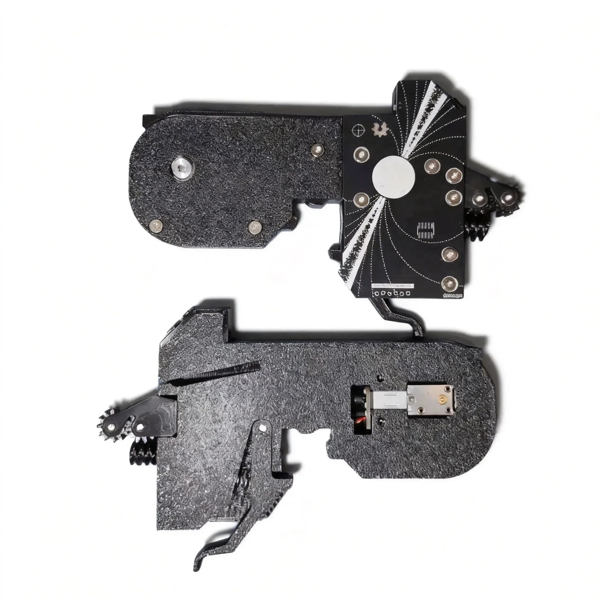
- Slot pads carry 24 V, the RS-485 bus, and a 1-Wire EEPROM holding that slot's address, which the feeder reads at boot.
- Spring pins bridge the pads to the board inside the feeder.
- The feeder board runs the Photon protocol and drives the stepper.
- The drive motor turns the drive wheel, through a cable that runs from the board to the motor.
- The drive wheel teeth sit in the tape's sprocket holes and index the tape 2 mm per feed.
- The peel motor lifts the cover film through the peel gears, leaving each part exposed in the pick window.
Steps 1 to 4 fail loudly, with a light or a status code. Steps 5 and 6 fail silently, everything reporting success while the parts land in the wrong place. Most wasted feeder swaps start as a step 5 fault treated as a step 1 fault.
The light already answered one question

A powered feeder goes red either at boot or a few seconds after you command a feed, and those are two different faults.
Red at boot means the feeder came up without a usable slot address, and nothing in the motor path has been tested yet. The causes, in the order Opulo's troubleshooting page lists them, are a bent or short spring pin, a pin that is not fully seated, dirty slot pads, or the feeder's pins making contact before the 1-Wire pin does. Clean and straighten the contacts first.
Red a few seconds after a feed means the feed did not complete. The delay is expected: the move is blocking, and the feeder reports when it finishes or gives up.
Four outcomes from one status byte
The Photon protocol does the exchange in two packets. MOVE_FEED_FORWARD (0x04) takes a distance in tenths of a millimetre and answers with the expected feed time in milliseconds; the host then polls MOVE_FEED_STATUS (0x06) until the move is done. A 2 mm tap is 0x14.
| What you see | What it clears | Where I look |
|---|---|---|
No reply at all, TIMEOUT (0xFE) | The motor path is still untested | Spring pins, slot pads, another slot |
UNINITIALIZED_FEEDER (0x03) | The bus and the board are alive | Rescan the bus, reseat the feeder |
OK to the move, then FAIL (0x05) on the poll | The bus, the addressing, the board | Tape jam, slack film, drive wheel, motor cable |
OK start to finish, parts still land off | The electronics | Sprocket engagement, feed pitch, crooked tape |
Rows three and four are the pair worth remembering. FAIL means the feeder told you its move did not complete, so the fault is mechanical and inside the drive path. A clean OK with a part in the wrong place means the feeder advanced exactly the distance you asked for and the tape did not follow, so the fault is geometry in steps 5 and 6 and bus debugging will get you nowhere.
Tape checks, before anything electrical
The cover film has to be taut. Slack film does not lift, so the part stays covered and the nozzle presses onto film. Loading tape ends with feeding the film by hand until it is tight.
Line the tape's cut semicircle up with the first tooth. Cut straight across an indexing hole. A cut that is not square puts the index off from the first feed, and the error accumulates down the reel.
Feed a newly loaded tape twice before trusting it. The tape settles into the guide over the first couple of feeds, which is why a feeder can test clean by hand and place badly in a job.
Look for film where it should not be. Cover tape caught between the worm gear and the peel gear damages the peel gear. On 16 mm and 24 mm feeders the outgoing tape can also catch the incoming tape and be fed back in, which produces a double feed.
On a PikkoBot powered feeder the pick window measures 5 x 10 mm at 8 mm tape and 8.5 x 14 mm at 12 mm, so there is room in there for a curl of film or a stray chip you cannot see from directly above. A torch and half a minute costs less than a feeder.
The ten-tap measurement
Every tap of the forward button advances the tape 2 mm, which makes the index measurable with a pen and calipers.
- Leave the tape loaded.
- Put a fine pen mark on the tape's top edge, flush with a fixed point on the feeder body.
- Tap forward ten times.
- Measure from the mark to the fixed point.
Ten taps is 20 mm. Measure 20 and the index is fine, which moves any misplacement onto pick position or nozzle height. Measure 18 and the wheel is skipping sprocket holes: the tape is sitting crooked in the guide, a tooth is damaged, or the tape was cut badly. Run the count twice, because one bad mark is easy to make.
The same button gives you the other half of the test. Press and hold forward with no tape loaded at all. If the feeder still trips red, the drive path has failed. Opulo's troubleshooting page uses this step to separate a tape jam from a dead drive motor. If it runs clean with the tape out, reload and go back to the film path.
Two readings from the meter
24 V at the slot pads. The feeder bus runs at 24 V. If a feeder is dead in one slot and alive in another, measure the pads before blaming the feeder. A slot reading well under 24 V is a machine fault that no feeder will fix.
Continuity through the drive motor cable, both ends unplugged, power off. A cable that is not seated all the way behaves exactly like a dead motor, which is why the manual tells you to reseat it first and why it is the most common false diagnosis on these feeders. Pull it off the board and off the motor, then read it end to end; an open leg is your fault, found in a minute. When you refit it, the crimp faces shiny side down and you push it home with a small allen key.
There is no published coil resistance for the drive motor, so a reading across the winding only separates open from not open. Continuity there clears the winding and sends you back to the cable, the wheel engagement and the tape.
Which part wears
Spring pins are the wear item on the electrical side. They need to be straight and all the same length when extended, and a few seconds with tweezers puts them back in line. Wipe the slot pads with the machine powered off, since wiping live pads is a good way to kill a feeder board.
To split a feeder fault from a slot fault, move the feeder. Red in the same slot and working two slots along means the slot. Red everywhere means the feeder.
The peel gear wears first on the mechanical side, faster when the film has been running slack and pulling sideways through the gears.
What OpenPnP does while you are looking somewhere else
OpenPnP keeps a feed retry count, and the job processor is stricter still: three faults inside six consecutive placements disables a feeder, and a single placement is attempted at most five times before the job fails. A feeder on its way out produces a handful of skipped placements and one disabled feeder, easy to miss halfway through a long job.
The order I use
- Look at when the light came on: at boot, or after a feed.
- Put the fault on the electrical or the mechanical side of the motor, using the status byte if you have the log.
- Run the tape checks, the ten-tap count, and the no-tape full-speed feed.
- Move the feeder one slot to split the feeder from the slot.
- Straighten the pins, clean the pads, reseat the drive motor cable.
- Swap in a known-good feeder last, and only to confirm a suspicion you already have.
The one time I went straight to step six I ended up with a good feeder on the shelf and a tape cut at an angle in the machine.
Numbers I keep on the shelf
The Vertex 4 has 50 slots at $1,499, so slot cost decides a feeder order as much as price does. An 8 mm or 12 mm PikkoBot powered feeder takes one slot; the 16 mm and 24 mm widths take two, which puts a 24 mm 4-pack at 8 slots, or 16 per cent of the machine. The 4-packs are $299 for 8 mm and 12 mm, $319 for 16 mm and $329 for 24 mm.
Tape width tolerance is ±0.3 mm on all four widths, and the nominal maximum tape depth runs 2.5 mm at 8 mm tape, 6 mm at 12 mm, 8.0 mm at 16 mm and 11.5 mm at 24 mm. A deep pocket can foul the guide on the narrow feeder even when the tape width fits, so check that number against the component datasheet before ordering wide tape. The full table is on the powered feeder page.
The rest of what I look up lives in the feeder overview for button modes and slot widths, the tape loading procedure for the film path, how many feeders a job needs for the reel count, mounting for rail positions, and the OpenPnP feeder setup guide for the software side.
A feeder that measures 20 mm over ten taps and reports OK is not what made the board wrong, and finding that out takes less time than walking to the shelf for a replacement.