Cut Tape, Half Reels and Splices: Incoming Parts on a Desktop PnP

Most of the tape on my bench never came on a reel. A hundred 0805 resistors arrive as a foot of tape in an antistatic bag; five thousand of the same part arrive in a sealed foil bag with a desiccant sachet and a card printed with three dots. The two are stored and loaded differently, and getting it wrong costs parts rather than time.
I keep three things next to the Vertex 4 for this: a flush cutter, a roll of splice tape, and a marker. Here is what each one is for.

How parts arrive
Cut tape. The distributor cuts a length off a reel and bags it, so the strip starts mid-pocket and has neither a leader nor a trailer in the EIA-481 sense.
A partial reel. Buy five hundred and you often get a part-used reel, with the bag opened at least once and sometimes closed with packing tape.
A full reel. Sealed bag, desiccant, humidity indicator card and a label carrying a bag seal date. Only this one tells you anything about moisture.
The two numbers that fix the geometry
Every sprocket hole sits 4 mm from the next one, and the hole centre is 1.75 mm from the tape edge, which puts the near edge of a 1.5 mm hole 1 mm inside the tape. OpenPnP uses those exact values: ReferenceStripFeeder ships with Hole Pitch at 4 mm and Hole Diameter at 1.5 mm, and the source hard-codes tapeEdgeToFeedHoleCenter at 1.75 mm with a comment naming EIA-481. The lateral distance from the hole line to the part centre is computed instead of typed: half the tape width minus 0.5 mm, so 3.5 mm on 8 mm tape.
Thickness is the other half of the geometry, and it decides how splicing and baking go. IQD, a frequency component maker that publishes its tape splicing service, quotes EIA-481 Table 2 for the two limits that matter at a joint: 0.6 mm maximum pocket tape thickness and 0.1 mm maximum cover tape thickness.
Cutting a strip so a feeder can index it
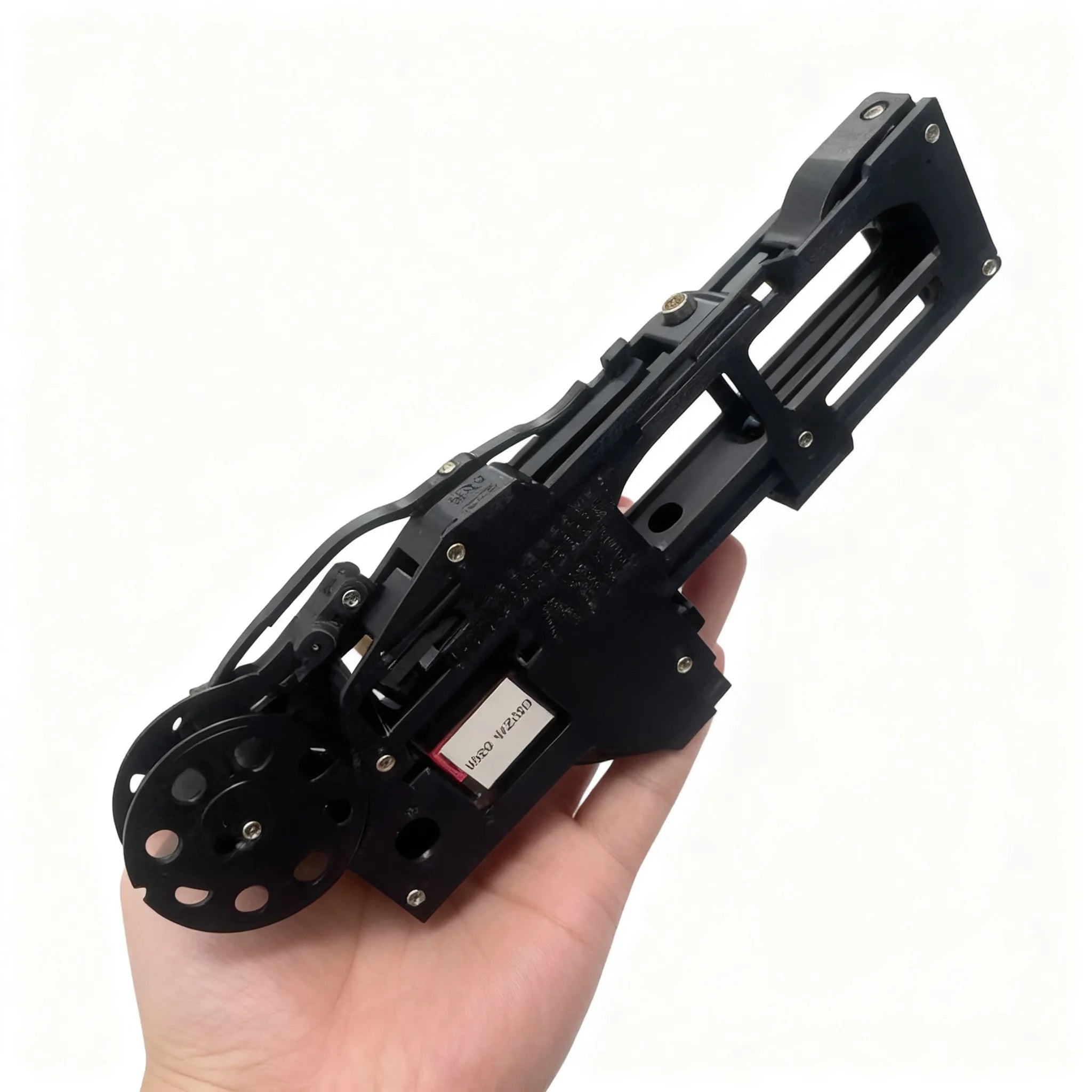
The loading tape guide covers the hardware sequence for a powered feeder, and the first step is the one people skip. Cut the tape straight across one of the indexing holes, leaving a semicircle, then align that semicircle with the first tooth on the drive wheel. Cut through a pocket instead and there is nothing for the wheel to index against, so the tape sits still while the button clicks.
From there the film matters more than the carrier. Peel a few millimetres back, feed the tape into the rear opening film side up, then hold the forward button and pull the film up so it separates from the pockets and wraps into the guide slot that leads to the peel gears. Two ways to damage a feeder live in that step. Film that points at the worm gear while entering the peel gears gets caught between them and can destroy a peel gear, and a fresh strip tends to lose its first few parts while the film is taken up. Opulo sells film extensions, adhesive-tipped film strips, to avoid that: stick the extension onto the end of your tape and trim it once it is past the gears.
Running a cut strip with no feeder hardware
Two software classes handle a strip on the plate, and neither uses a slot. ReferenceStripFeeder is built for tape: capture the reference hole location and a second hole further along, vision confirms holes as the job progresses, and the pick locations are interpolated between them.
What surprises people is that the part pitch is never read from the pockets. The source computes holeCount = round(measuredDistance / holePitch) and scales from there. If the two calibration points end up less than one hole apart it falls back to the hole pitch, with a comment noting the setup is wrong but has been tested to behave reasonably. Two errors tell you what happened: run past Max Feed Count and the feeder throws Feeder <name> empty.; lose the hole sequence and vision gives up with Unable to locate reference hole. End of strip?
Vision only accepts a candidate hole within narrow windows: diameter up to 1.1 times the configured 1.5 mm, pitch at least 0.9 times the configured value, hole line within 0.5 mm of the expected one, and a found hole no more than 2 mm from where the last one predicted. A hole punched off pitch, a pocket cut through the middle of a hole, or a joint that pulls the tape sideways can push the next candidate outside the window, and the strip ends early with parts still on it.
Because the pitch is inferred from the two points you calibrated, an interruption in the hole sequence shifts every position after it by the same fraction. That is why I site a splice behind the reference hole instead of in the middle of a strip I still intend to run on this feeder.
ReferenceTrayFeeder is the fallback when vision cannot see the holes at all. Two counts and two offsets turn the strip into arithmetic, and the first-board walkthrough uses it for a cut strip of resistor tape with the Y offset at -4 mm for the 4 mm pocket pitch and a 1 x 30 count. The off-tape feeding article covers the Z conventions for both classes, which differ.
Joining two pieces of tape
IQD's splice note is the clearest published description of how this is done: the butt ends of the pocket tape are joined with a metal staple, and the cover tape is joined with a sticker over it. Their tool is a stapler-type splice tool, and the note states the process conforms to EIA-481, against the 0.6 mm and 0.1 mm limits above.
The ends butt together for a reason. An overlap stacks two pocket tapes and two cover tapes at one spot, up to 1.2 mm and 0.2 mm, and that lump has to travel through the peel gears and then under the drive wheel. A staple holds the joint close to a single tape thickness.
Two checks before a spliced tape goes into a feeder:
- Count the holes across the joint. The sprocket pitch stays 4 mm, so the holes either side of the staple have to land on the same grid. A half-hole error is 2 mm, which is exactly the distance at which the strip feeder's vision declares the strip finished.
- Same width, same part number, and label the reel. Two lots of the same value on one reel is fine for a prototype. Two different values on one reel is how a board gets a resistor from the wrong decade.
The film extension in the loading guide solves the same waste problem at the other end, when new tape needs a leader rather than a joint.
The clock that starts when you open the bag
J-STD-033 is the document behind the desiccant and the dates on the label, and the two dates do different jobs. The bag seal date starts a twelve month shelf life when the bag is stored below 40°C/90% RH. Opening the bag starts the floor life clock, and its length comes from the moisture sensitivity level: MSL 1 is unlimited at 30°C/85% RH, MSL 2 is one year, MSL 2a is four weeks, MSL 3 is 168 hours, MSL 4 is 72 hours, MSL 5 is 48 hours, MSL 5a is 24 hours, and MSL 6 has to be baked before use, then reflowed inside the time on its label. Every value except MSL 1 is quoted at a factory ambient of 30°C/60% RH or better. Those come from Table 5-1 in the standard; the online summaries tend to drop the ambient condition.
The clause that changed how I store parts is 5.2. After a partial lot, the rest has to be resealed or put into safe storage within one hour of the bag being opened.

Miss that hour and clause 4.1 says a dry cabinet or dry pack does not by itself pause the clock, which catches people who assume a dry box resets everything. For MSL 2, 2a and 3 exposed for twelve hours or less, 4.1.2.1 gives the recovery rule: desiccate for at least five times the exposure time, in a bag with desiccant or a cabinet at 10% RH or better, and the clock resets. MSL 5 and 5a use the same idea with an eight hour threshold. A cabinet at 5% RH or drier counts as a sealed bag with unlimited shelf life; a 10% RH cabinet only buys the limited time in Table 7-1.
Read the indicator card as soon as the bag opens and at 23 ± 5°C, and scrap it once the 60% spot reads wet. Levels 2 through 5a are still dry when the 5%, 10% and 60% spots all read dry. If the 5% spot is wet, the 10% is not dry and the 60% is dry, then levels 2a through 5a need drying while level 2 stays usable. A torn bag with a card past its limit goes to a 48 hour bake at 125°C (clause 5.1.1).
Baking numbers for the MSL 3 parts I keep hitting: at 125°C, a package body of 1.4 mm or thinner needs 9 hours if the floor life was exceeded by more than 72 hours, and 7 hours if it was exceeded by 72 hours or less. The same two cases take 13 and 9 days in a 40°C oven at 5% RH or better, which is what I use for parts still sitting in carrier tape. Before a 125°C bake the standard requires removing external wraps, rubber bands and plastic tray ties. Two rules that matter on a two-sided board: reflow and rework do not reset the clock, and a component gets three reflow passes at most.
The 8 mm versus 12 mm tape page has the rest of the EIA-481 dimensional limits if you are choosing widths. For storage my routine is unglamorous: marker the seal date and today's date on the bag when it is first opened, reseal partial reels with the original desiccant, and keep the reels that matter in a dry cabinet rather than on an open shelf.
What a cut strip saves you
None of the strip work above uses a feeder slot, and that is where the accounting matters. A part placed once or twice per board does not earn a slot on a 50 slot machine. The feeder count page works through the numbers from four real boards: slot budget goes to the line items and the wide parts.